
gallo magnetix
JX-3P+ Information
Expanded MIDI Implementation, Enhanced Functionality.
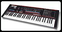
This project began with the aquisition of a JX-3P for $100.00.
As a Hybrid Synthesizer, their are two domains to exploit for feature enhancement; the Analog section and the Digital section. The Analog section comprises the audio component, the Digital section comprises the control component, of this instrument.
A goog WEB source for schematics, commentary and, recommended modifications can be found upon Florian Anwander's WEB site.
The Digital opportunities within this instuments are;
This project efforts are within this Digital Domain.
This project expects to create a evolved version of the JX-3P which is more inline with current expectations for a microprocessor based device.
STATUS:
Presently the Schematics are being "re-captured" and a Source Listing is being generated.
Milestone One:
Produce a revised EPROM of evolved functionality within in the EPROM capacity of 8K. As the firmware of the JX-3P occupies virtually all of the existing 8K EPROM, a function will necesarily have to be removed. The TAPE function are traded for MIDI SEQUENCER Store and Recall.
Speculatively, the JX-3P deploy's a "vanilla" 8051 microcontroller. This mirco is the heart of this instrument. Feature enhanced versions of this micro exist with wide variety. Further enhancements, based upon a microcontroller replacement are easy to predict;
All of this opens the door to the introduction of more software implemented function blocks such as ADSR's, Individual modulation sources (per DCO), Portamento, etc. Modern 8051's implement FLASH or E2ROM capability that eliminates BATTERY BACKED Preset Storage.
Events to Date
In the effort to create a JX-3P+ the requires a use-able Schematic and a practical software source listing for the existing JX-3P implementation. My JX-3P was fitted with a CMOS ROM (2365) which i have yet to read effectively with either of my two EPROM Burners. While dealing with this issue, i was contacted by Oliver Dahlmann.
Oliver presents a great WEB Site which is replete with a binary image of his EPROM, a Rich Text annotated reverse assembly, and a lot of JX-3P Register Level technical information.
A visit to Oliver's WEB Site is recommended to anyone interested in the technical architecture of the JX-3P.
Oliver's JX-3P Site
Status
Source Listing in progress, it began as a source listing from the reversed assembled binary file posted and produced by Oliver Dahlmann. This source listing assembles with most industrial strength 8051 assemblers but is specifically targeted toward the METALINK ASM51 assembler. This 8051 assembler is freely downloadable, assembles standard intel syntax & directives and is also very good and fast.
Soon I will post the source listing. Presently it assembles but is not fully segregated into DATA and CODE, it's riddled with variables and flag bits yet to be understood. Work does continue (07/19/02).
 Frequency Source:
A single JX-3P Voice implements using 2 DCO frequency sources. Each DCO implements a standard "Integrator-Reset" sawtooth oscillator. A standard Op-Amp integrator is periodically discharged by a transistor switch which "shorts" across the integrating capacitor. The switching transistor is itself driven by a pulse eminating from one channel of an i8253 Programable Counter Chip. The frequency at which the capacitor is discharged set the frequency of the oscillator.
The 8253 Timer provides 16 bit's of division of a single Master Frequency. This is not enough to cover the full audio range. To expand the range of the DCO, it's Master Oscilator has a programmable binary divider which allows for "octave" range setting. This type of circuit is often referred to as a Prescaler. As each Voice is comprised of two DCO's, Each DCO of a single voice pair has a different Master Oscillator frequency standard. This allows an independant octave agility for each of the two DCO's (which comprise one voice). An idealized depiction of the DCO component of a single JX-3P voice can be seen here
Implementing "Portomento" or "glide" requires a smooth transistion between two frequencies must account for OCTAVE RANGE as well as INTEGRATOR VOLTAGE and TIMER DIVISOR values.
The Figure on the Left depicts a single DCO circuit
The control voltages for each Voices VCF, VCA, DCO Reference Voltage, DCO, Resonance, etc all require a wide range voltage control. Also, Six Channels worth of voltage control.
The control voltages for each Voice originates at a "BUILT OUT" 12 bit DAC. This DAC provides control voltages for the VCF/VCA and the Integrator Current for the DCO's.
The DAC is comprised of a pair of hex-latches (loaded with a 12 bit pattern encoded upon [DATA 0-7] and [ADDR 4-7]. These Q outputs of these latches drive two resistor "packs". Each Latch bit drives a node or a 2R summing matrix where D7 drives a series resistance = "R/4092; D6=R/2048, D5=R/1024, D4=R/512 ... A4=R"
If R=1 Meg then D7 drives 244 ohms this is why DQ7 and DQ6 are buffered.
This resulting voltage is the weighted sum of the stored bit pattern. This voltage is buffered by an OPAMP which has an offset adjustment to "center" voltage.
The figure on the left depicts the DAC ciruit.
 Voice Voltage Distribution
The DAC is multiplexed (more properly "de-multiplexed") by CMOS switches which act as "Sample and Hold" switches. The purpose of this is to distribute a specific set of control voltage to each Voice, without providing a 12 bit DAC for each control voltage generated. Instead, the microcontroller periodically incrementally outputs current parameter voltages to each of six Voice circuits. Each new period outputs to the next of six Voices rolling over to the base Voice after six.
The Micro presents the current parameter voltage to the DAC selected the channel and parameter to update (which opens the sample switch" then "opens" the switch depending upon a capacitor and a "selected for low leakage" TLO type op-amp to retain this voltage until the next time around where it is "refreshed".
The specific Muliplexer depicted is that which provides an adjusting Integrater Voltage to DC01 of a dual voice circuit.
The figure on the left depicts the Voice Mux
Conclusions So Far:
Can the PG-200 and MIDI co-exist?
JX-3P owners are well aware of the back panel switch which selects MIDI/Protect/Programmer. This switch implements hardware that exclusively provides a path for either the PG-200 or MIDI. This indicates that at a minimum hardware modification to allow concurent use of these remote "host" devices would be required.
Beyond this, the microcontroller, which is the heart of the JX-3P, provides only 1 serial data port. As the format of the serial word size is different (PG-200=9 bit data, 1 stop,No Parity; MIDI= 8 bit data,1 stop, No parity) tricky programming would have to occur to "merge" these data streams.
However, once mastery over the JX-3P code is demonstrated selection of a two serial port micro (ds320,420,520 or like) and some re-committment of signal pins could allow concurrent PG-200/MIDI.
Does the base architecture allow for full independance of the 6 Voice Pairs?
No. The JX3P architecture implements many controls "in common" across the six voice circuits.
Examples of the implementation of "common controls" are:
While fairly wide range independance of frequency for each voice can be achieved, independance of tone color is more problematic. Other enhancements are however achieveable notably a second ADSR, independant LFO per Voice (or even DCO, MIDI SysEx and CC Msg parameter control and Portamento.
Noticably, the MUX's is not "built out" fully. A small circuit addition which added 4 additional Sample and Hold buffers could allow for separating Resonance to, perhaps, two Voice Sets, meaning 3 Voices have one Resonance Setting and an alternate 3 Voices would have another. This could also be done to the Wave form Select and Source Mix voltages.
Available Information:
Good Schematics have yet to be found for the JX-3P so i have reproduced the Florian Anwander schematics. I have posted pages which i am incrementally "cleaning up". I update these pages often, as "clean up" proceeds.
Schematic Pages
JX3P Schematic Sheet 9
JX3P Schematic Sheet 8
JX3P Schematic Sheet 10