
Dual VCA
Revised: 4 Sept. 2003 - Added missing 1M resistor in Figure 4 Lin/Exp VCA (vca_layout.gif)
Overview
Analog Devices' SSM2164 quad VCA integrated circuit is intended for audio control applications such as mixing desks, compressors and limiters. It represents a high quality alternative to standard OTA based audio circuits.
SSM2164 Datasheet
Design Challenges
In order to apply the SSM2164 for traditional format voltage controlled synthesizers some characteristics of this integrated circuit must be compensated for.
Traditionally, analog synthesizer VCA's;
Notably, the SSM2164;
Linear VCA
Maybe you saw the July 25, 2002 issue of EDN where Mike Irwin's Design Idea presents his simple yet elegant technique for linearizing the SSM2164 VCA.
Op-Amp Linearizes Attenuator Control Response.
 Using Mike's "servo" technique, positive input voltages invert and offset exponentially against the Voltage Reference connected to the input of his Master Cell. The resulting output voltage controls other SSM2164 gain cells with linear dB/V proportionality.
The schematic as shown is a simple but high quality addition for a DIY synthesizer's VCA "core".
Using Mike's "servo" technique, positive input voltages invert and offset exponentially against the Voltage Reference connected to the input of his Master Cell. The resulting output voltage controls other SSM2164 gain cells with linear dB/V proportionality.
The schematic as shown is a simple but high quality addition for a DIY synthesizer's VCA "core".
Do note the circuit, as shown,
Compensation for the signal inversion could often be an additional inverting op-amp. This amp could precede the R3 input node providing both a non-inverting audio path but also standard synthesizer 100k input impedance if desired.
Alternatively, an additional inverting amplifier could follow the output amp correcting phase, as well as, provide for balanced output.
DIY Envelope Generators are likely to easily accomodate the 0-15V control range. However, changing the reference voltage input to the Master Cell (VREF) to equal the maximum voltage expected from the controlling envelope generator (or other modulator) accomodates a wide range of sources. This reference must be of opposite polarity however (i.e. -5 reference for a 0 to +5 envelope).
VCA Implementation
The figure below shows one approach to implementing this VCA for +/-12V power supplies and 0-5V control voltage range.
The Control and Audio op-amp's are shown as separate I.C. packages to allow optimization for the VCA specific purpose. Use of a precision DC amplifier in the control loop (i.e. OP270) could also accompany the use of a low noise, high output drive capable op-amp (NE5532) for the audio path. The circuit does work quite well, however, using TLO7x/LF35x operational amplifiers.
Notably, the majority of components shown are for power supply de-coupling (some of which you might omit as a function of your supply and layout characteristics).
While the following page describes a hard wired, point to point VCA implementation, there are commercial implimentations of this core design available across the internet. Those that credit Mike are probably good choices for a high quality VCA.
Note:
Three commercial offerings that derive from this design can be found at:
Exponential Control Response
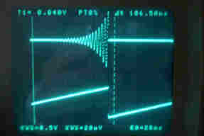
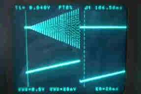
Synthesizer VCA's often provide both a linear and exponential response. The images below depict an exponential, then linear control response to a sawtooth control voltage. When the sawtooth control voltage is "below ground" the VCA is off.
Exponential VCA
As the native response of the SSM2164, an exponential response synthesizer appropriate VCA should implement easily but, as noted above, the control characteristics deviate from those typical of analog synthesizers.
The circuit depicted below implements increasing gain with increasing control voltage, provides a 0 to +5 VDC response range, and provides the same unity gain characteristic for max control level as did the linear implementation.
The graphic is obvious a "mark-up" of the linear VCA shown above and as such is somewhat "idealized" as it ignores two VCA's in the quad package.
The circuit shown below attenuates the input 0 - 5V control swing to the ~ 2 volt range that is effective for the SSM2164.
A variable positive voltage offset connects which set the degree of attenuation for Envelope OFF (0vdc).
As an envelope progresses from 0 to +5V the an increasingly negative voltage drives the SSM2164's gain cell.
In response to this progressively negative voltage the SSM VCA reduces attenuation.
The variable reference can be exploited to:
Ensure maximum Envelope Level in Linear or Exponential mode is of equal level.
Exploit the greater dynamic range of Exponential mode perhaps for short envelopes.
Alternate Response VCA
As can be guessed from the above diagram, a composite of both techniques can be implemented allowing the selection of either a linear or exponential slope. A DPDT switching arrangement is required. If this is done using a conventional front panel switch, the switch should mount directly on the circuit board to avoid routing the non-inverting input of the control circuit through a lenthy wire path. Alternatively, electronic switching could be done.
Analog Switching and Control Voltage
The Master Gain Cell, when biased OFF, results in the control amplifier running essentially "open-loop".
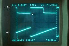 As Mike's description declares, the amplifier will swing close to the positive power rail, in this case. This is depicted in the figure on the right. As shown, a positive control slope into the VCA results in a shallow negative slope which drives the SSM2164 gain cell to produce decreasing attenuation. When the sawtooth control voltage proceeds below ground, the master cell amplifier snaps to near the positive rail.
This signal swing must be accomodated by any analog switch applied, a standard CD4016/4066 switch would not be suitable. Analog switches, able to handle this signal range, exist from many vendors, however, their "ON Resistance" is large enough to require "trims" to achieve best performance. Also, this on resistance can change with applied voltage rendering trims a compromise at best. A zener diode could be placed across the feedback capacitor to "shunt" this voltage and reduce the requirement for the selection of an analog switch.
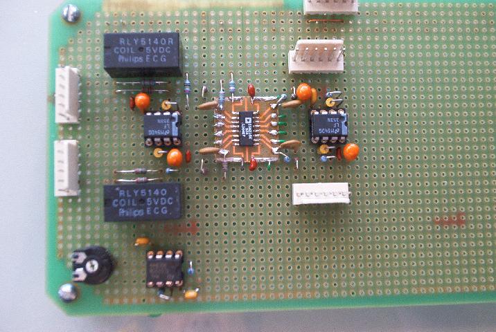
In the implementation depicted below, simple board relays were used to allow rapid implementation without concern for careful consideration for analog switch components and the compensitory trimmers that would be required.
The use of the relay's to perform the circuit reconfiguration allows the front panel switch requirement to reduce to a single pole switch remoted by any reasonable length of wire, or (as is the case in my specific MGB project) by an automated interface.
The circuit depicted below has been constructed and verified for use as a high quality, dual-channel, linear/exponential synthesizer VCA component.
Tweaking
The resistor on the SSM2164 Mode pin (#1) should ideally be 6K for optimal Class A operation (1.92ma) when using +/-12 Volt power. Additional filtering in the form of a larger cap in the feedback loop of the control voltage op-amp U1 could be implemented if noise coupling occurs at this circuit node.
Summary
A point to point, of this dual channel VCA design has been made and can be viewed
here.