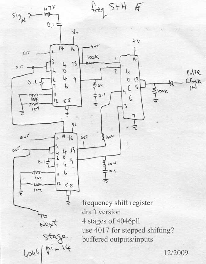
frequency shift register
This is still a draft version and needs a lot of refining, but the basic idea works well.
The Analog Shift Register is well known, where voltages are shifted over three stages. This is the same in concept except it shifts frequencies and uses 4046 PLLs to do it.
Which means you have to be very optimistic to expect to see the frequency you fed into stage 1 to appear at stage 4.
For a single audio input and a clock signal, it produces 16 audio (or CV/gate/trigger) outputs of related frequencies.
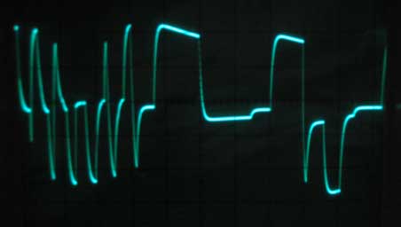
March 2010: Here is an UNTESTED draft of the full schematic. The circuit has been breadboarded with two 4046 stages and certainly put on a performance.
The clock ticks over the 4017 decade counter which enables the 4046 PLLs to shift their frequencies to the next stage.
first clock shifts PLL3 to PLL4, 2nd is PLL2 to PLL3, 3rd is PLL1 to PLL2 and 4th allows a new frequency to be introduced to PLL1.
Or you can feedback one of the outputs from PLL4 and get a loop going....oh yes:-)
But don't expect any kind of perfect tracking, these are 4046s. Your loops will drift horribly at best or just generally misbehave.
The frequencies are shifted by connecting the comparator outputs to pin 9 of the 4046s. The 4017 counter allows the 4066 switches to close in turn. The frequency from the comparator is smoothed to a voltage by the 10k resistor and 0.1u cap.
Once the 4066 switch opens, the voltage in the cap is held thanks to the hi-Z input on pin 9.
This voltage on pin 9 determines the frequency of that PLL's VCO.
Bindubba 2 pdf [vers.2](72kB)