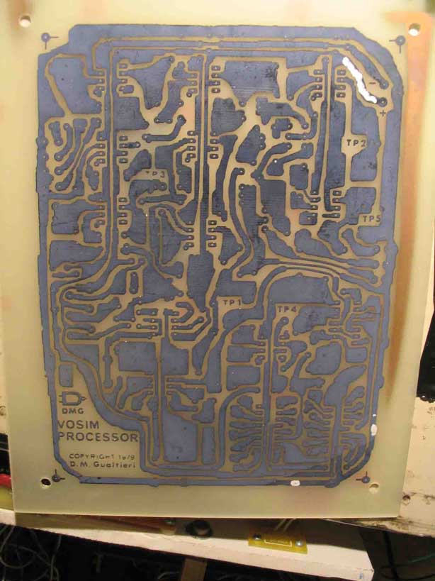
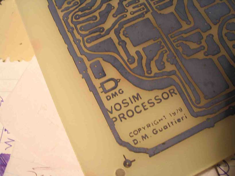
The Vosim Processor was presented in Electronotes (EN#130) in an article by Dev Gualtieri. The circuit implements a VOice SIMulation technique developed by W. Kaegi & S. Tempelaars in 1978. The EN article included a PCB design and a required component was the AD533. As this chip is no longer available I made some changes so AD633 could be used. Then, as my board was PnP went and filled as much space as possible, partly as it is easier to do the transfer, quicker to etch and why waste all that lovely copper?
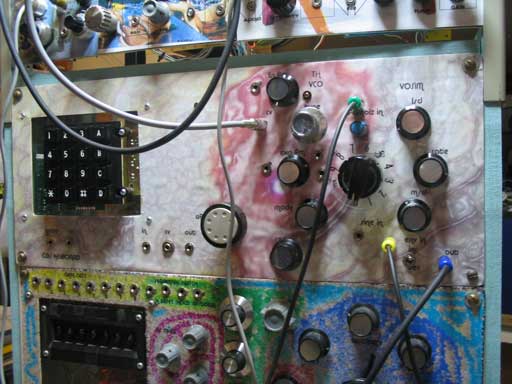
These two samples were made using a TH VCO-1, controlled by Ian Fritz's Jerkster Chaos, then the VCO plugged into and sync'd by the Vosim
vosim1 2.1Mb mp3
vosim2 4.5Mb mp3
I have not found any reports of others building this circuit, so thought it may be worth documenting the build, working or not. The schematic will not be posted - go buy Electronotes. Sometimes Bernie will post a single issue if asked nicely. I will seek permission to post the modded PCB design, once tested.
***there is a small error in the EN PCB layout, the 43k resistor between the collector and emitter of MPS-A13 should connect to -15V NOT 0V. there is a -15V track nearby so it is a simple job to fix.
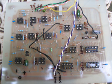
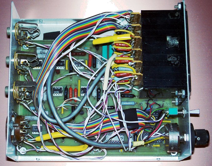
As seen below this cct is finished (tho not yet panelled - 12/09 - panelled! see minisyn) and works well. The article is very helpful as it gives indications of what waveforms should be observed at different testpoints. As the article states, this circuit is capable of a huge variety of sounds. it is unlikely you will get anything intelligible out of it, but we have samplers for that anyway.
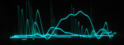
output of the AD633, poor pic but want to show it runs from 0V to approx 5V at double the input freq.
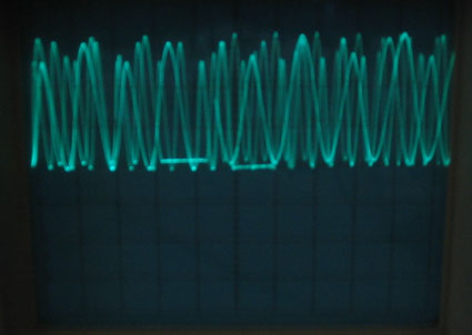
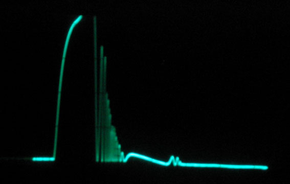
This pic shows the output of the VOSIM before adjusting the DC offset, the bright spot at the bottom of the 1st wave is an audible click
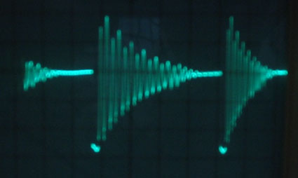
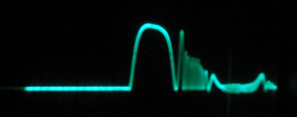
The three pictures below show the signal once the DC offset is adjusted properly, no initial click can be heard.
usual dodgy vid
27/9/2010 - Dev Gualtieri kindly sent some pictures of the VOSIM he designed and built back in 1977
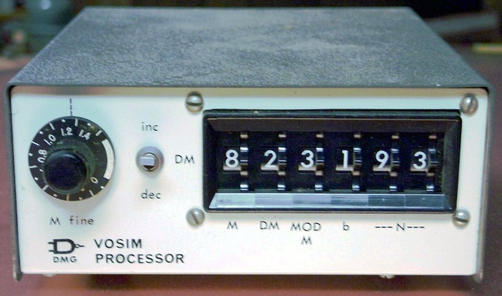
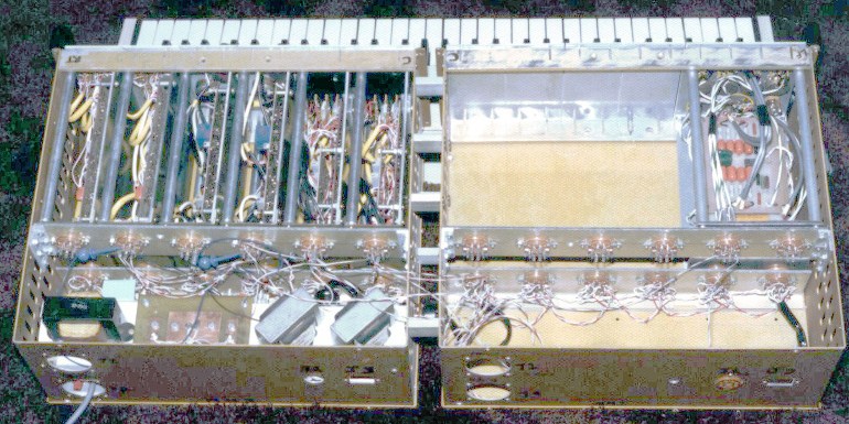
Thumbwheel pots made from thumbwheel switches and resistance ladders.
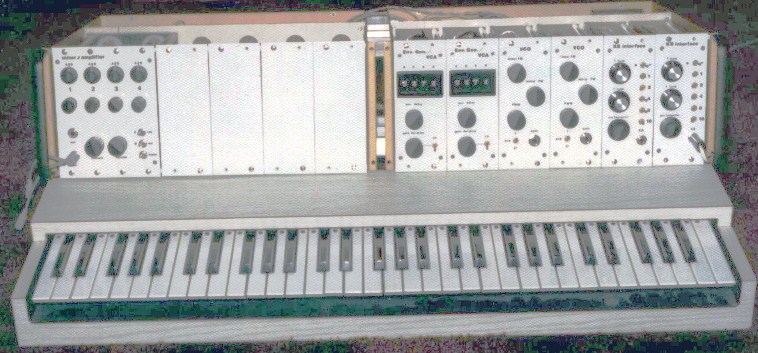
This was Dev's self-designed DIY synth, his description of the modules is: " 1) Keyboard interface with binary switches to transpose up or down 35 semitones. 2) Same as (1) 3) VCO with FM modulation input and pulse-width modulation input. The outputs were the sine, triangle, square and pulse. 4) Same as (3) 5) ADSR envelope generator using thumbwheel switches to set A,D,S and R and a pot to set envelope delay. The VCA was included in this module 6) Same as (5) 7) Four channel mixer and stereo power amplifier Not shown in the photo, since they weren't yet finished, was a ring modulator module, two voltage controlled filter modules with LP, HP and BP outputs and a module with two utility oscillators and a noise generator."
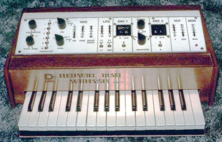
Another synth designed & built by Dev.
Thanks very much for sharing these pictures & for the VOSIM circuit!