
MG-1 Concertmate Synthesizer.
MG-1 User Information
Duane Kitchen's VCO Frequency Adjustment
Duane's LFO Frequency Adjustment а (Text document).
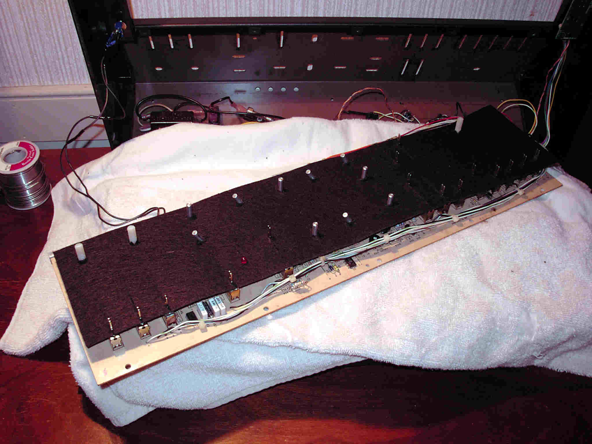
Duane's Control Panel Gasket Solution (pix)
Shayne's MG-1 Archive
This page presents methods for increasing the capability of the Realistic MG-1 Concertmate.
The MG-1 is a compact synthesizer with buried possiblities for enhancement.
The following paragraphs deal with different stategies for simple exploitation of existing architectural capability:
The MG-1 was conceptualized and produced as an integrated synthesizer within the general model type also exemplified by the moog Rogue, Prodigy and Liberation synthesizers. аExamination of divergent capabilities or characteristics, of these synthesizers, may suggest ideas for inclusion into a increased capability MG-1. аThe buried potential of the MG-1 is greater than may initially be apparent. аThe oscillators afford a wider range than is suggest by the integrated keyboard, the low pass filter is effective, and the Sample and Hold/ LFO do augment the single AD/R envelope generator.
Native Architecture а
Ignoring the Keyboard Electronics, the figure below conceptually depicts the MG-1 architectural components. аNot shown, is the method by which the "organ" voice is involved with the generation of the keyboard "GATE" signal which triggers the Envelope Generator.
In summary the MG-1 implements:
A Note About Keying
The MG-1 envelope generator depends upon the "ORGAN" voice for keying or triggering. аThe Organ voice audio is rectified and filtered into D.C. for On/Off key detection and input to the AD/R envelope generator.
 The MG-1 keyboard provides 2 contacts per key. а
One contact devotes to analog synthesizer pitch (or main control voltage) which drives the VCO's. аThe second contact directly switches on/off, one organ note per key. а Any sounding organ note switches to a common summing bus where notes combine and route to both the MIXER as the organ voice, but also, to a key detection circuit.
It is the detection of, at least, one close organ key contact that triggers the MG-1's envelope generator.
The circuit that performs this Key or GATE signal generation is depicted in the figure below.
Routing of Raw Organ Audio : аA pressed key routes raw Organ audio (0 to +12V) to the U17a summer which attenuates the A.C. coupled Organ notes (level set by R42). а This output drives the "Polyphonic" fader of the MG-1 audio MIXER. аThe output of U17A also routes to U17B where it is re-amplified and applied to a rectifier/filter (CR1, R46, C6) providing a reference voltage for the U8 comparitor. а With a key depressed, this reference voltage is above U8's 1 Vdc comparitor theshold (set by R48/49) and U8 emit's a -12VDC "key-on" signal. аWhen a key is released this reference voltage falls below this threshold (as a result of R47 rapidly "leaking" potential from C6). аIn this case U8's emit's a positive (+12Vdc) "key-off" level. аIf the Organ voice re-triggers or is inconsistant it would be likely that the value of C6 is no longer "in spec".
Implication of Organ Voice Keying:аThe reason for this detail is to point out that when a MIDI to Control Voltage interface is fitted to the MG-1, there is no contact closure to route the Organ voice to the audio mixer. а Additionally (and normally) the MIDI2CV interface must provide an S-TRIG signal to activate the internal Envelope Generator.
MG-1 Mains Voltage:
An MG-1 can be configured to accept either 120 or 240 VAC as mains power. As depicted in the figure below for 120VAC mains the transformer's primaries are wired in parallel. а240VAC requires the Primaries to wire in series.
An excerpt from the schematics depicts this:
RAW VCO Waveforms:
 The MG-1 VCO provides either a Sawtooth or Square/Pulse waveform outputs. аIncreased versatility would result from the addition of a triangle waveform.
The MG-1's sawtooth waveform, if brought to an external patch point, would be a good source from which to derive a triangle waveshape. аAn external circuit comprised of full-wave rectifier, centering and, gain circuits, produce a tri-angle waveform of equal signal swing to the incoming Sawtooth wave.
The figure right depicts a circuit, external to the MG-1, that would accept the MG-1's sawtooth waveform and use a full-wave rectifier to "fold up" the negative excursion of the Sawtooth waveform generating a "uni-polar" tri-angle waveform. а Following this a gain of two amplifier and an Offset trimmer result in the final waveform. аThe depicted trimmer is a board (non-panel) control which allows adjustment to ensure the waveform "offsets" 0V.
If a sine wave where desired, the triangle waveform is a common signal from which to derive one. аIf the triangle was allowed to overdrive and following differential stage, a sine of ~ 1-2% purity could be achieved.
If the waveshapers are to return to the MG-1 "pre-filter" then an input to the MIXER need be derived.
Polyphonic Audio Processing:
 The Organ voice could also benefit from external processing prior to MG-1 MIXER.аState Variable filtering, or the much maligned "bucket brigade" shift register are examples of typical Organ audio enhancement.
аIn particular, the noise typical of BBD circuits is rendered less objectionable due to fixed signal level (and thus fixed S/N altered only by specific delay time) and the following MG-1 24 dB/8ve Low Pass Filter.
The Organ voice could also benefit from external processing prior to MG-1 MIXER.аState Variable filtering, or the much maligned "bucket brigade" shift register are examples of typical Organ audio enhancement.
аIn particular, the noise typical of BBD circuits is rendered less objectionable due to fixed signal level (and thus fixed S/N altered only by specific delay time) and the following MG-1 24 dB/8ve Low Pass Filter.
Again, a normalled connection routing the organ voice external only when a cable is inserted, routes the Organ voice to additional processing and returns the result to the Polyphony slide fader.
Pulse Width Modulation:
 The "stock" MG-1 provides two square waveforms one at 50% and the other at 10% pulse width. а The MG-1 circuit board incorporates a "trim-pot" for adjusting the the 50% VCO square wave width. аRemoting this as a front panel control would allow manual Pulse width adjustment. а Alternatively, this trimmer could be "normalled" through a two circuit jack and allow a remote controller to apply a 0-10Vdc modulation voltage.
The figure right depicts the circuit board trimmer adjustment.
The second MG-1 VCO does not incorporate a trimmer. а instead a fixed voltage divider implements a 10% duty cycle square wave. аIf remote operation of this VCO's pulse width were to be required, the R46/R47 values should be changed to the R18/R19 configuration of the first VCO.
Normalling MG-1's Mixer Inputs
 Despite it's front panel location, the MG-1 Mixer preceeds the filter. а It combines the audio from VCO, Noise, "Bell Tone" and Organ voices. а
Here's a busy graphic which attempts to depict patch points which intends to route the "pre-fader" audio source external using "normalled" patch point routing. аThe absence of an inserted patch cable results in standard MG-1 routing.
Despite it's front panel location, the MG-1 Mixer preceeds the filter. а It combines the audio from VCO, Noise, "Bell Tone" and Organ voices. а
Here's a busy graphic which attempts to depict patch points which intends to route the "pre-fader" audio source external using "normalled" patch point routing. аThe absence of an inserted patch cable results in standard MG-1 routing.
The "switching" jacks depicted in the graphic allow the routing of MG-1 sources external and then back to the MG-1 Mixer. аExample functionality would be where an triangle waveform was developed from the Sawtooth waveform (also depicted as a patch available output) and switched against the standard Saw and Pulse waveforms for additional VCO versitility. аAnother example would be the "stone cold" Organ voice being routed to external modification and back to the mix.
Increasing Audio Level:
 The audio output level of the MG-1 is very low. аDue to this low audio level, it is not uncommon for MG-1 users to drive the audio chain from the Headphone output jack of the synthesizer.
The LM386 headphone amplifier does impart artifacts that may or may not be considered useful. аIncreasing the audio output level can be easily occur remedied by removing R102 (1K). аThe removal of this resistor results in a 10x level increase as the CA3080 VCA's output load resistor is now the end to end value (10k) of the Master Volume Control. аUpon removal of this resistor, the MG-1 output is now ready to drive standard a standard audio chain with reduced distortion compared with the Headphone amplifier output.
The figure right, depicts, schematically, the location and connection of R102, highlighted in Red.
External Audio Input (Pre-Filter):
The MG-1 has no native provisioning for external input prior to the VCF or VCA components of the synthesizer. аIn addition two RCA inputs are made available to allow a "passive" mix of external audio with the output of the synthesizer.
The following reference links to a text document describing the re-allocation of one of these available input as an input to the VCF input summing.
Carl Virtanen's External Input Modification
Non-invasive enhancement of the MG-1 exploits:
External Control Strategy
The MG-1 VCOs have a range that extends beyond the integrated 32 key manual. аA standard analog keyboard (providing S-TRIG) extends MG-1 pitch possibilities and provide missing pitch bend control. аMIDI to Control Voltage interfaces, or especially those that incorporate "modulation", opens the MG-1 to devices and applications such as Sequencers, Arpegiators, and a wide mix of external keyboards.
Independent Amplitude Control:
Another useful non-invasive enhancement is perform the final VCA amplitude shaping externally. аA VCA with at least, one ADSR modulator, extends the expressiveness of the MG-1 considerably. аThe "freeing-up" the integral AR/AD Envelope generator provides independant control of the Filter.
To add an external VCA the MG-1 must be switched into "continous" key mode. аThe internal VCA is now always on while the Filter responds to the AD/R envelope. аThe same controller that provides S-TRIG to the MG-1, need also activate the external VCA's envelope extending the synthesizers range of articulation.
Modulating the "ORGAN" Voice:
As pitch modulation was only provided the MG1's VCO's, the Top Octave Generated Organ Voice is "stiff" by comparison.
The figure right, depicts schematically the location and connection of the MG-1 integrated Modulation Level potentiometer, highlighted in Red.
 The wiper of the Modulation Pot connects directly to the VCF through R106. аA wire connected directly to R106 at the "wiper" side can be routed to the Master Frequency Reference. аThe "Poly Reference" provides a point where the VCO within the PLL chip can be effectively modulated.
It must be recognized that the ORGAN Voice and the VCF will be modulated simultaneously but the level of modulation for the VCF will not "match" the in "excursion" the Organ Voice Vibrato.
The Master Reference is located on the Keyboard Electronics Board underneath the Keyboard Manual, it's Reference Designator is U1.
аThe figure left depicts the junction of R1 and R2 which is the point where the wiper of the modulation pot connects.
Radio Shack Concertmate MG-1 Schematics:
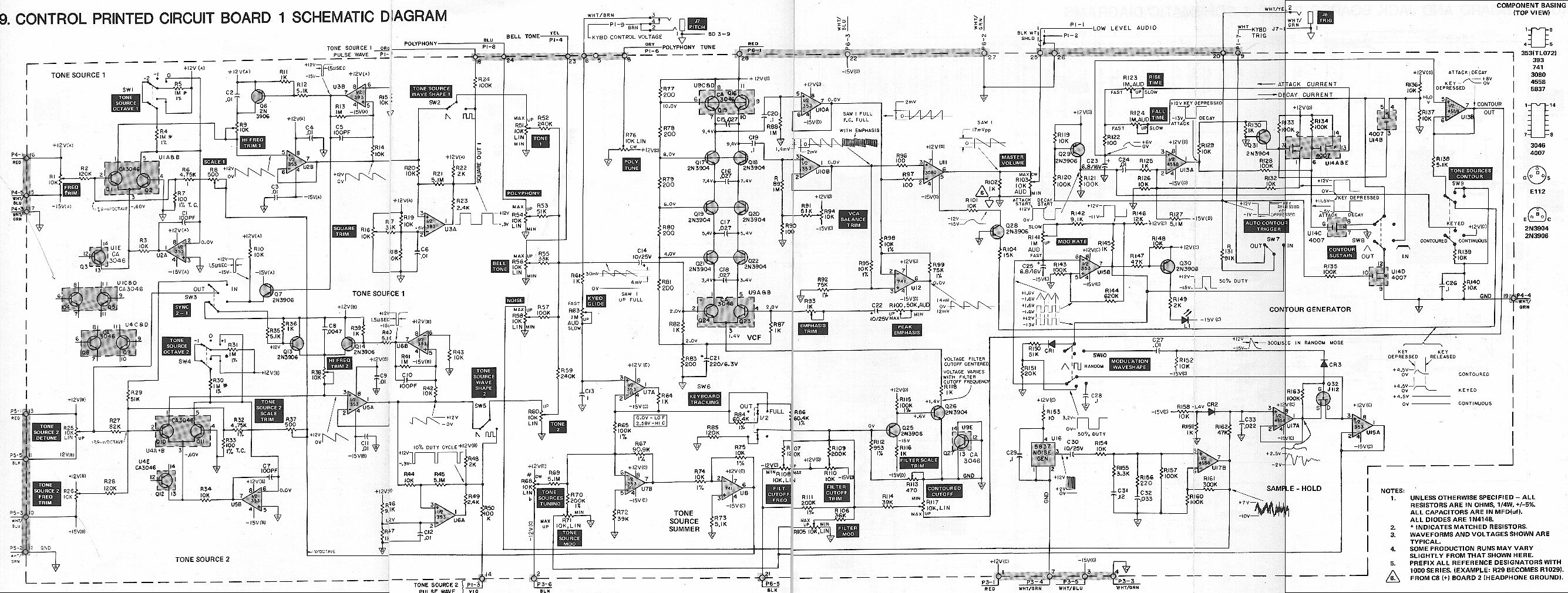
MG Voice Circuitry
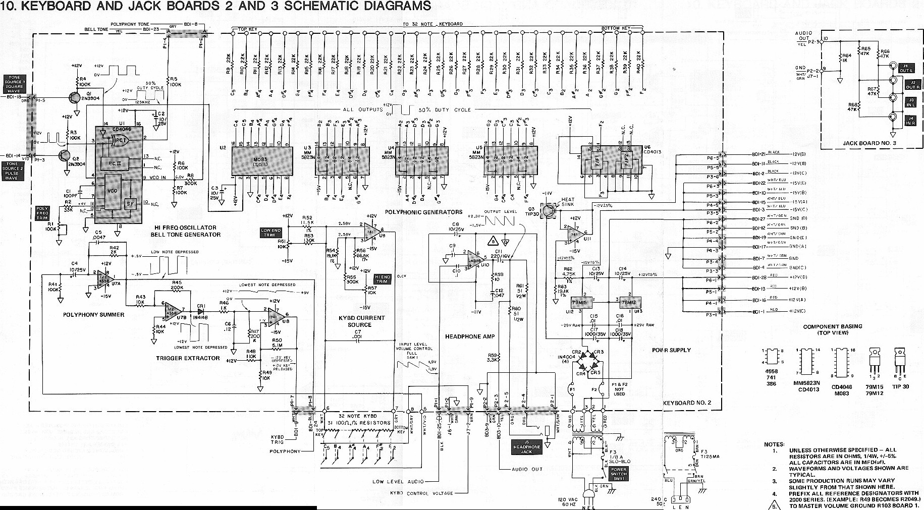
MG Key-Control Circuitry