Summary of Functional MGB Hardware Components:
| Two VCO's |
- Working
- Sine;
- Sawtooth;
- Triangle;
- PWM Square waveforms.
- Remaining to do:
|
| Ladder Filter |
- Remaining to do:
|
VCA's
ĀTwo Switched Lin/ExpĀ
ĀOne Linear
|
- Allocation
- VCO Level Mix VCA
- Post-VCF Final VCA
|
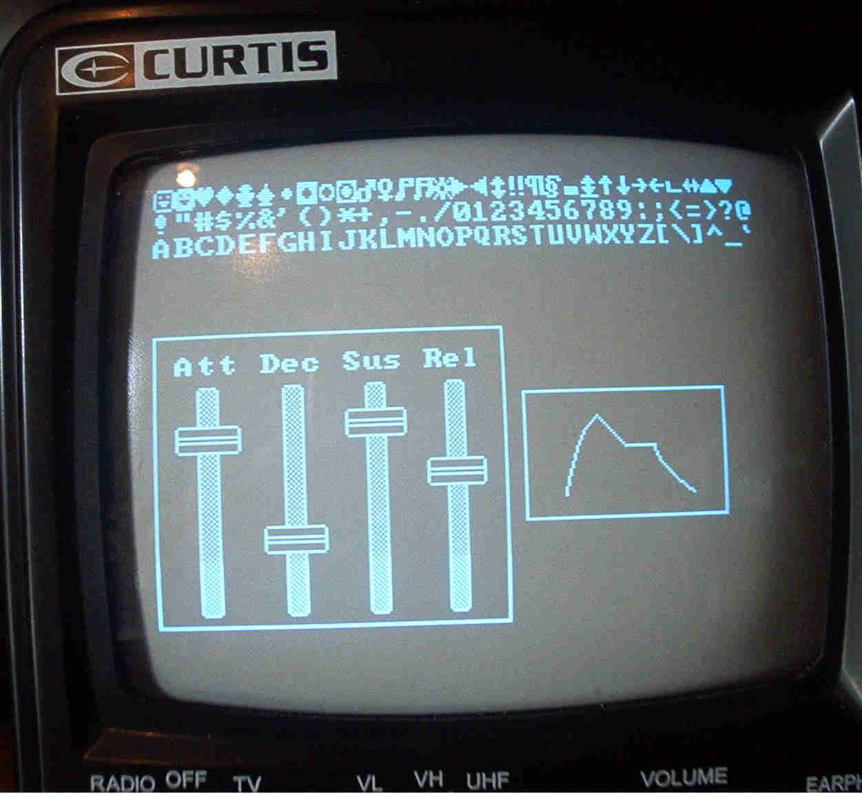
| MSC1211 EVM PCB |
- Currently Generating:
- Three 8-bit ADSR Control Signals
- One 8-bit Noise Signal
|
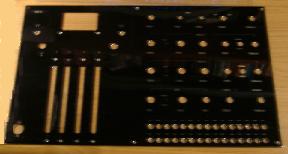
| Mezzanine Board |
- Status:
- DS80C420 micro Responding
- Downloadable @ 16MHz MHz using MS-DOS TTY Downloader
|

 The MGB Host Processor provides 16 bits of control voltages for: