Accept - a short track made with Tube synth and Korg ES1
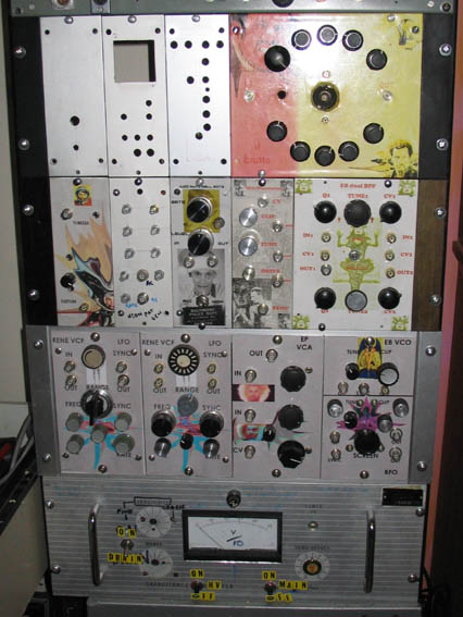
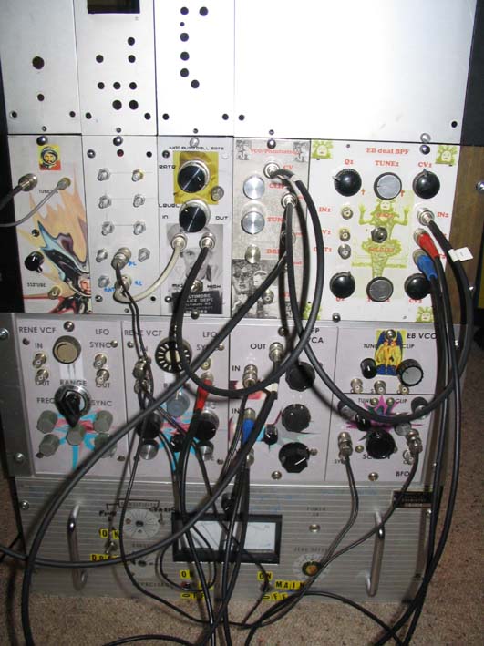
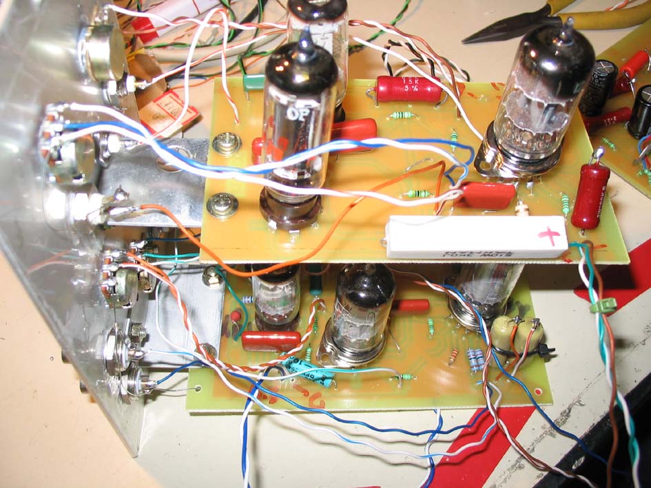
Synth as of 27/3/2009
Tried out an idea to run the dekatron sequencer with a relay circuit, also simplified the outputs to just a pot wired as a divider on each dekatron cathode, from the pots' wipers run 1n4004 diodes all joined together and connected to the output socket.
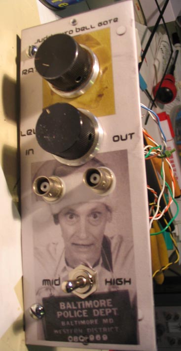
The relay works best driven by the neon LFOs with signal conditioning by Judd's bell gate, can get it to run as fast or slow as I like.
The bell gate can also be set so the dekatron steps forward one stage at a time, jumps around semi-randomly, or steps between just 3 or 4 stages...though it is pretty hard to choose WHICH 3 or 4 stages.
Here's a pretty ramshackle vid, mainly made to show off the noise from the relay. The relay's clacking does not enter the soundpath if recording the synth into a sampler or whatever.
11/12/2008
Built a pattern generator using 8 neons. Each neon sits next to a LDR, the LDRs are wired as voltage dividers with 10K pots as the lower section. One output is 0-25V, the other output is +/-10V, runs thru a 6021 wired as a cathode follower. A 1M pot sets the voltage driving the neons, which also sets the patterns and sequences that result. Some are very simple, just triggering three bulbs, others are totally unpredicatable.
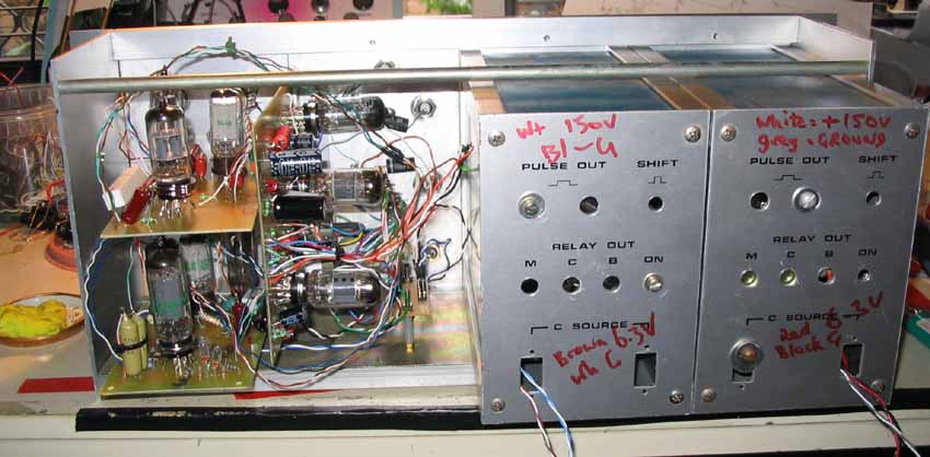
Also started building my long threatened dekatron sequencer. Built 450V PSU, the trigger circuit uses a (you guessed it) 6021 dual triode (a shop in Tokyo gave me 65 of these for free). It works but not how dekatrons usually work. Most trigger circuit for dekatrons are for a constant frequency - usually mains 50Hz or 60 Hz. I have got it to work with one of Eric's VCOs, changing the frequency doesn't mean the dekatron spins faster or slower, it needs two trigger signals about 45deg out of phase...anyway, needs refining. Check out the vid at the bottom to see a confused dekatron.
5/12/2008
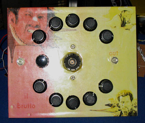
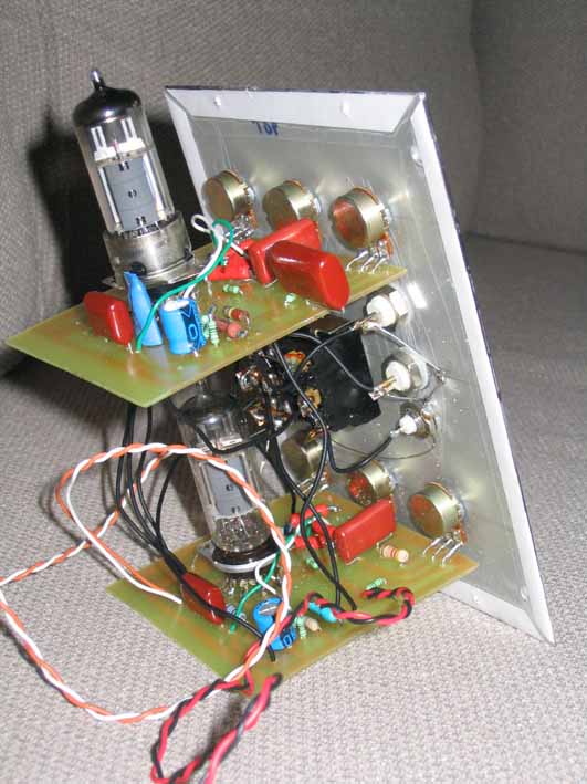
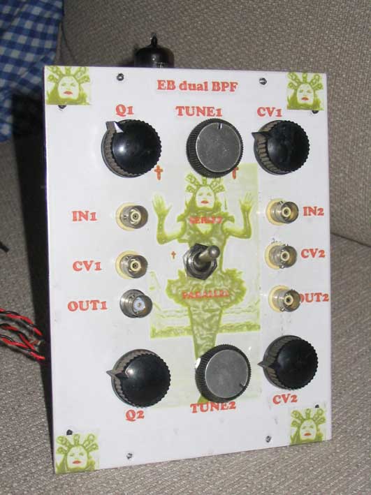
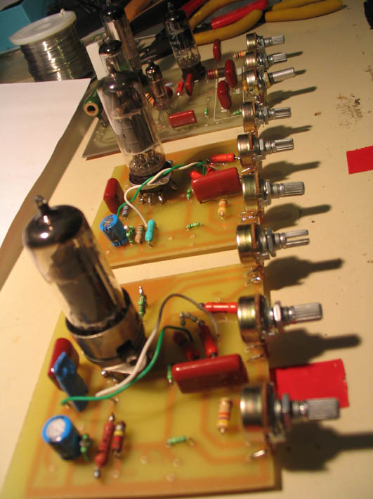
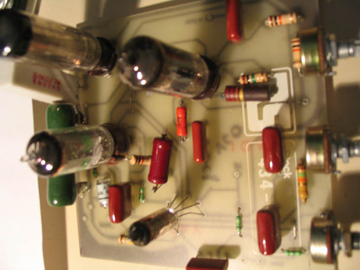
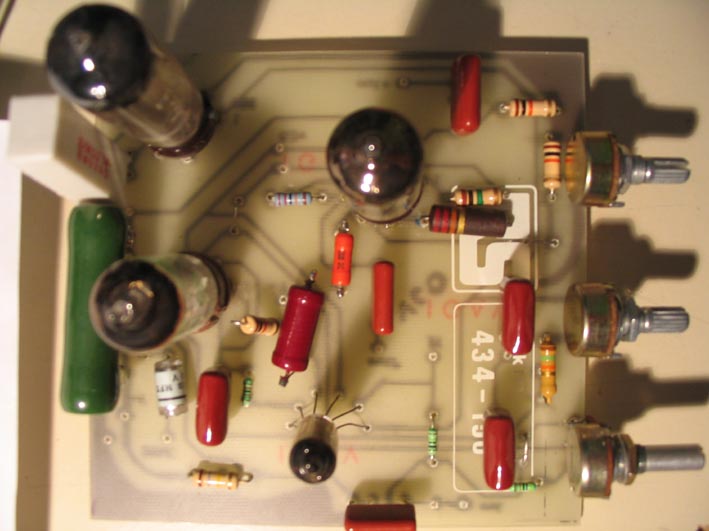
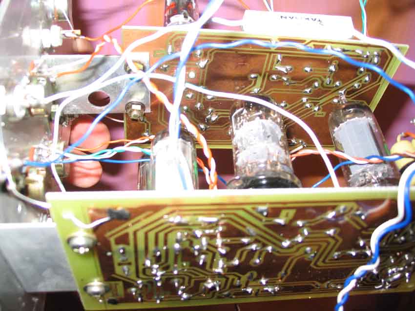
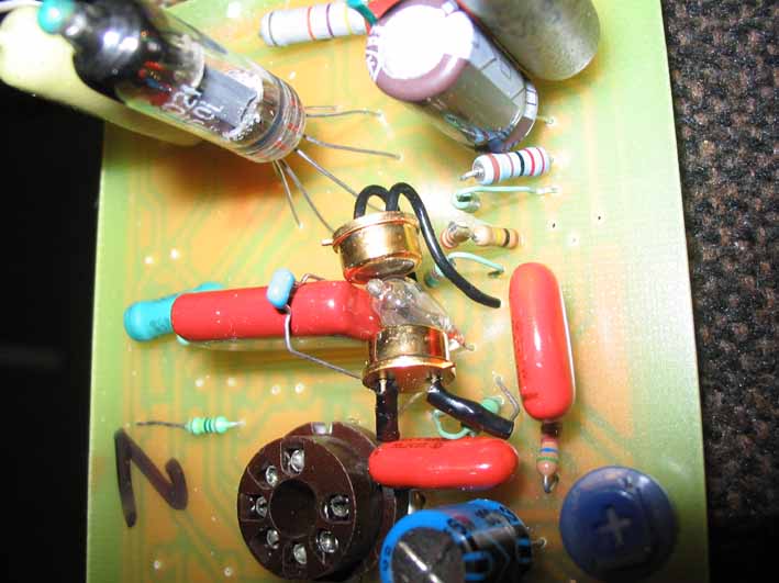
Etched two PCBs for Eric Barbour's (METASONIX)bandpass filter, the intention is to be able to switch between cascaded and parallel filters, used 6DX8 tubes which contain pentode and triode sections.
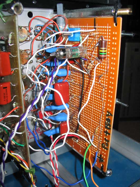
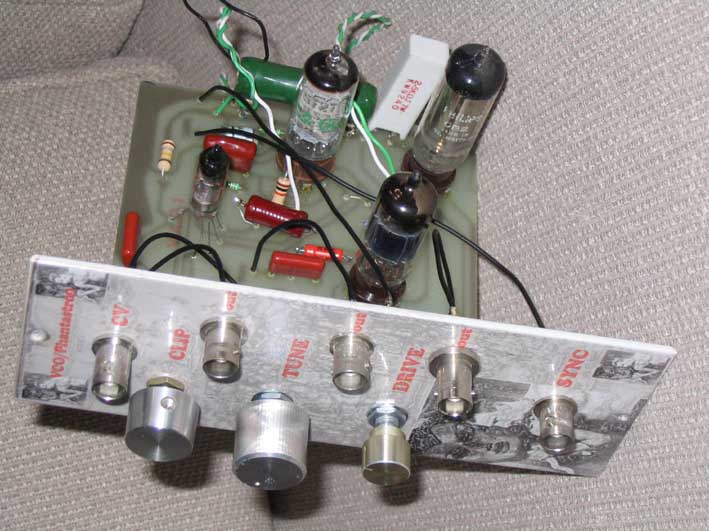
Also etched a PCB for another thyratron VCO with a Phantastron output section. The circuit is from an old (obviously)CSIRO book on radar. Inspired by Lorin E. Parker of Electric Western. Lorin sells kits to build your own Phantastron. This PCB uses a 6021 sub-mini dual triode, 5727, 0B2 and 6AM6 for the Phantastron.
No special reason for choosing these tubes, other than there are a few of them in the cupboard. I am getting really tired of wiring up modules, so designed these PCBs with the pots mounted on board. Pix below.
8/9/2008
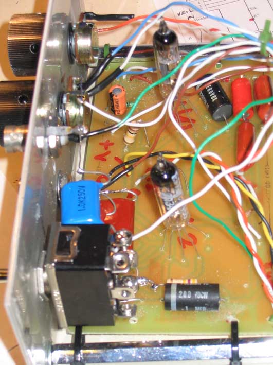
Added Judd's Auto Bell Gate - att/rel generator of sorts
31/8/2008
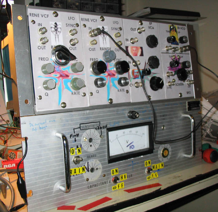
found some shelving brackets which serve nicely to make a rack for the panels, so added 2 pix.
7/8/2008
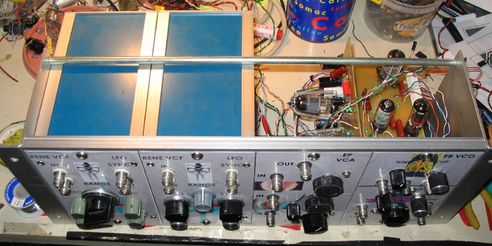
Finished the first section of this synth
The PSU uses a pooter power supply to get 6.3V for the heaters.
The main supply is +/-150V, this will be expanded as necessary.
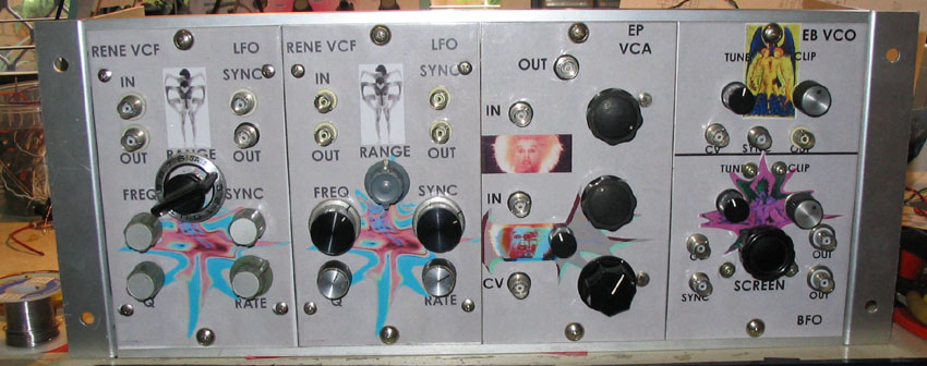
Modules so far -
Two Eric Barbour (METASONIX) VCOs, schematics from CGS synth.
One of the VCOs has Eric's beam modulator built into it,
with two neon LFOs to do the modulating. The other is stock.
Two René Schmitz VCFs (with some help from René - Thanks!)
using 6021 submini triodes and 6AU6 pentodes.
These have sync'able neon LFOs driving the LDRs and outputs for the LFOs.
I have found these LFOs to be capable of chaotic behaviour when tuned carefully.
The VCFs can get a nasty liquid scream happening.
The VCA/mixer is from the Electronic Peasant's tube synth page. It is VCA #2 & #3 with the 600:600 transformer on the output. It works perfectly and sounds great. EP should be complimented for such a great design.
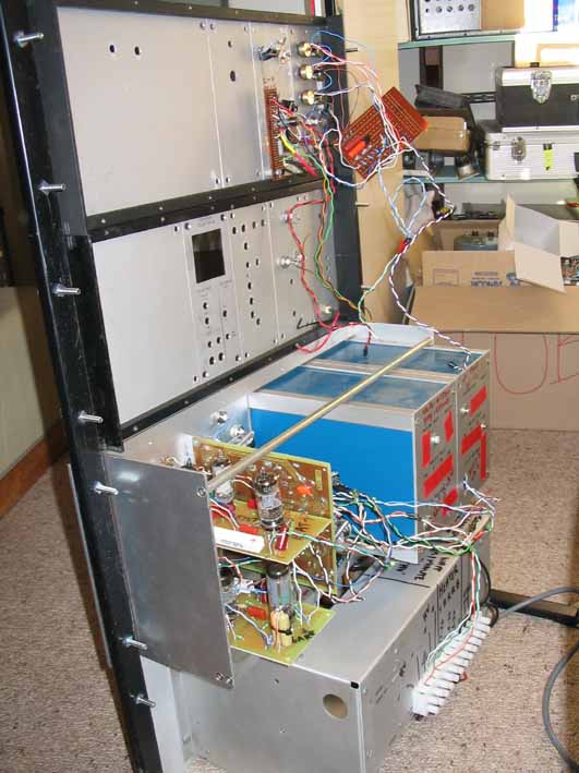
All connections are BNC. There is an interface panel with 3.5mm to BNC, via a DC amplifier, and BNC to 3.5mm, via a voltage divider. So far I have designed and etched PCBs for all of the modules as I intend to make a few more of each. The synth is built into 19" racks (from the Physics dept. dumpster as usual), so it will be easy to expand as time permits.
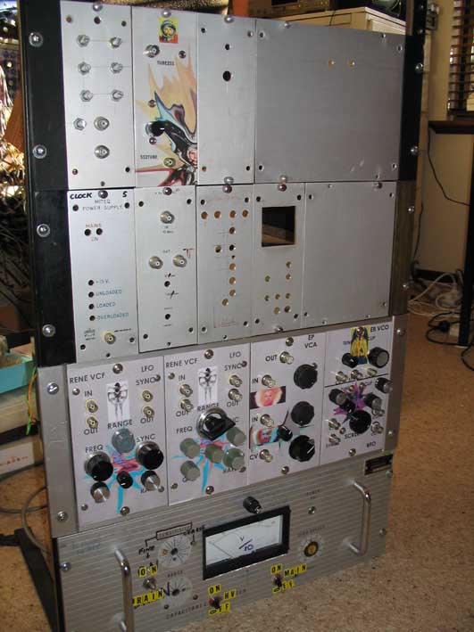
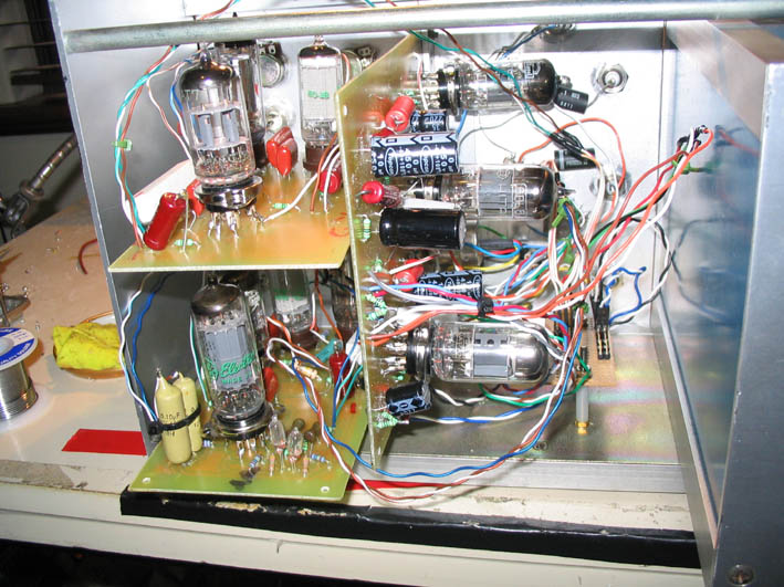
dekatron sequencer...still having fun trying to get it to trigger at a range of frequencies. As of 11/12/2008 neon-LDR pattern generator, the neon bulbs and LDRs are inside the blue shrink-wrap BPF boards mounted dual BPF completed VCO/Phantastron BPF, BPF, VCO/Phantastron VCO/Phantastron VCO/Phantastron The world's greatest movie director! Bell gate PCB and panel, more controls have been added since this Pic was taken...trying to get more functionality out of it, other than 90V spikes. The blue boxes house the VCFs which have LDRs, so need to be shielded from ambient light. Genghis Khan PSU is on the bottom. One switch is to turn on the tube heaters, 2nd is for the 'high voltage', 3rd is to drain the capacitors quickly - really only needed when I am working on it. Inside the blue boxes -the LDRs came from an old HP digital multimeter, the thing had nixies and weighed about 15kg, found it on the side of the road.