DR-110 Hand ClapThe microController generates a burst of 3 low-going triggers 10mS apart on CPI, followed by a single trigger on CPII. Transistors Q16 and Q15 invert these into high pulses to generate envelope voltages. C48 and R108 create three quick envelopes each having a 10mS decay. (See: Check Point 10.) Through R111 and D14 these envelopes provide a CV as the collector voltage for Q12, acting as a VCA. The resulting audio that appears at D14 anode passes through R115 to the bandpass (hi pass?) filter formed by Q24.
Sometime after the 3-pulse burst, CPII occurs, C49 produces an envelope with a longer decay (Check Point 11,) than the "burst" envelopes because C49 is larger than C48 and does not have a resistor in parallel with it. This envelope reaches Q12 through R112 and D14. This longer decay envelope, occuring after the burst envelopes, partly causes the pseudo echo effect -- but the '110 designers didn't stop there.
At the same time that C49 is producing a CV, D16 and C50 create an envelope with an even longer decay. (Check Point 12.) The audio that appears at D15 anode has less harmonic content than that at D14 because C51 slightly lowpass filters it. The resulting audio that reaches Q24 is at a lower level than the other path because R114 is twice the resistance of R115. (The third duty of Q12 is as VCA for Snare noise, which will not be described here.)
I believe the two delayed, "after" envelopes are what make the pseudo echo so effective.
 Click to hear Clap
The hi-lighted components in the above schematic are where modifications can be made. "Tune" and "Pitch" change the levels of the burst and echo audios. "Phaser" affects the Center Frequency of the bandpass filter, and as such is more of a pitch adjustment than the points labeled "Tune" and "Pitch" are. Decay controls the duration of the final echo. C50 can be increased to further extend the pseudo echo duration. Dan Lavin's modified Hand clap
http://www.theninhotline.net/dr110/resFreq/ http://machines.hyperreal.org/manufacturers/Boss/DR-110/mods/dr110-clap-snare.txt http://www.vidiotsquad.com/synth-stuff/dr-110-mods/ http://www.theninhotline.net/dr110/110mods.html
Cloning...can be complete, or partial ("quasi-"), and can include any of the modifications previously discussed -- or even some new ones. I have two rules specifically about DR-110 clones:1) NO sharing of VCAs between instruments 2) NO sharing of filters, either I''ve had some success on breadboard with a partially cloned HiHat, and will describe that later.
Cloned MetalClose, but no cigar. I think I should *HAVE put more work into the band-splitting filters.The notes given to the left of each oscillator are approximately what the frequencies listed in the Waveforms table are equal to. (Between C# and D, between G and G#, etc.)
 Note that I did not mix in White Noise here. I preferred to do that at the HH and Cymbal VCAs so that they could have different amounts of Sizzle. I call it that because "hiss" is normally something undesirable. I chose to not make the filters variable, for reasons repeatedly mentioned in the HiHat and Cymbal descriptions. I have an idea for band-splitting of the metal mix that does not involve filters, and will describe that in the section on MY HiHat "clone." *PET PEEVE: There's no such thing as "should of". So stop. Just. Stop. Generic Hi-Hat CloneIf active-high triggers are available, from whatever source, the PNP inverters Q1, Q2 can be omitted. Q3, buffering the Open envelope voltage, can also be omitted, but if it is then C8 should be increased, otherwise the voltage will decay too rapidly to be considered "Open." 2.2uF to 4.7uF is about right.
 I've said I don't see much point in having a Closed Decay pot, but I include it here for "completeness." If it's omitted, C7 should be 1uF or less. I also include the separate White Noise "Sizzle" option. The 1M? resistor may need adjusting, depending on how "hot" your WN is. In MY sample (next page,) it was 9V! Much less goes a long way. The filter (not shown) can be a duplicate of the DR-110 hi-pass (Q8) or some other hpf or bpf design, if preferred. Attenuation of the Metal signal will be necessary if the level is greater than about 1.5V because that would distort.
Paradigm X's (electro-music.com) Liquid HiHat/Generic Hi-Hat Hybrid
gen_lhh1
gen_lhh2
gen_lhh3 At what point in changing a design does it stop being a clone of the original?
Cymbal CloneI don't have any example of an actual '110 cymbal clone. The obvious action would be to copy the circuit and include any desired modifications as described on the previous page. I can, however, show what I would like to have:
 pretty cluttered drawing -- so cluttered that I now think something simpler might be just as versatile For the most part it's just what I suggested: a copied '110 Cymbal with some of the already described mods. I've made two changes, the most significant being changing the output filter to the configuration shown. I've heard what that particular filter can do to noise and other signals and am very impressed. Another change is a second trigger, so that the ping can be triggered separately, imitating striking a cymbal near the central bulge, called the Bell. (The wider part of a cymbal is called the Bow.) For that I've drawn a simpler 2-part decay circuit as used in the 606 and 808 cymbals. There's a Sizzle input for the body sound but not for the ping, because I'd want that to be purely metal when sounded alone.
(Although made with my partly successful partly cloned Hi-Hat, this sample demonstrates metal without white noise.
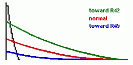
When the pot is 3/4 towards R45, 25k is in series with 10k for a total 35k; close to the unmodded value of R45. 75k will then be in series with the R42 changed to 22k for a total 97k; close to the original 100k. As the pot is rotated toward R42, the total resistance decreases, causing a higher level CV for Q7, increasing the loudness of the ping long decay. At the same time the resistance towards C21 increases, increasing the body attack time. C21 charges to a lower voltage than it normally would,
When the pot is rotated more toward R45, the resistance to the ping side increases, reducing the CV to Q7, and reducing the level of the long ping decay. The resistance on the body side decreases, allowing C21 to charge faster, and thereby reaching a higher voltage than normally, increasing the
(Neither envelope will be as simple as shown in the two illustrations, because the voltage from Q6 has a decay of its own, which can be varied.)
The values shown for R42, R45 and the pot may not be optimal; the pot might need artificial tapering in the form of fixed resistor(s) from wiper to either end. And if it turns out the whole idea is less than phenomenal, the "standard" mods will provide more than enough variety..
That's enough for one page. Cloning continues on Next Page.
|
 If this works as expected, then one more thing to try is controlling the balance of body and ping levels AND the BODY ATTACK with one pot, as shown over there -------->
 decreasing the CV that reaches Q9, thus lowering the body volume. Furthermore, because when C21 discharges it's from a lower voltage, the body decay time is shorter. Add one more parameter being controlled by one pot.
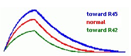 body volume. When C21 discharges, it does so from a higher voltage than normally, and so takes longer. Body decay time is made longer.
 softhome.net