Back to Projects
An Idea Whose Time Has Passed?
DAC (Revised again, 2013)
Another area where economizing is possible is in the Digital to Analog Converter.
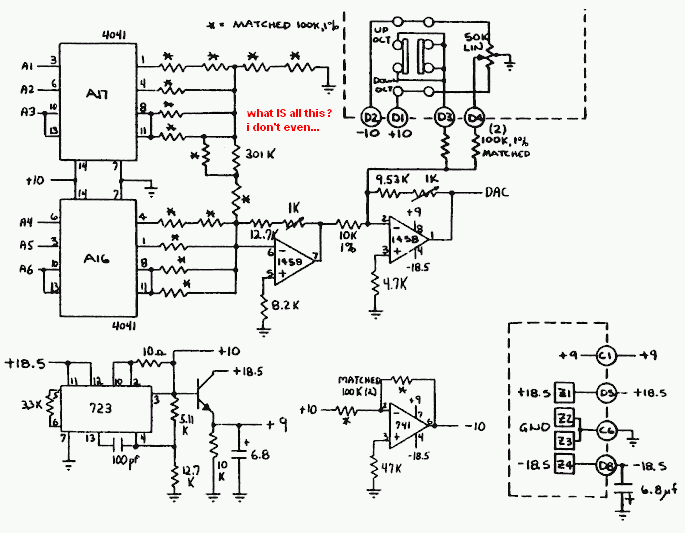
I don't know what's going on in that resistor network. Looks like two binary-weighted (2R, 1R, 1/2R) networks stuck together. Sort of. I don't see any advantage over a straightforward R/2R network OR to using two ICs. (Quad true/complement buffers, ignoring the complements.) And what's with all those voltages?
Call me Mr. Simplify.
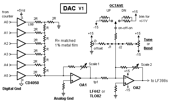
The hex buffer scheme has been proven to work. I used it in my modified Electronotes Digital Keyboard way back when and it worked just fine. After matching 1% resistors to 0.1% as best as I could I formed the 2R resistors by putting pairs in series. I could've instead formed the Rs by paralleling paired resistors. The resistor values aren't as important as that they all be closely matched.
Note that in both the Oberheim CD4041 method and the CD4050 circuit, the ICs' supply voltage is the DAC Vref. In my EN kb the 5volt logic supply (a 7805 voltage regulator,) was stable enough for that.
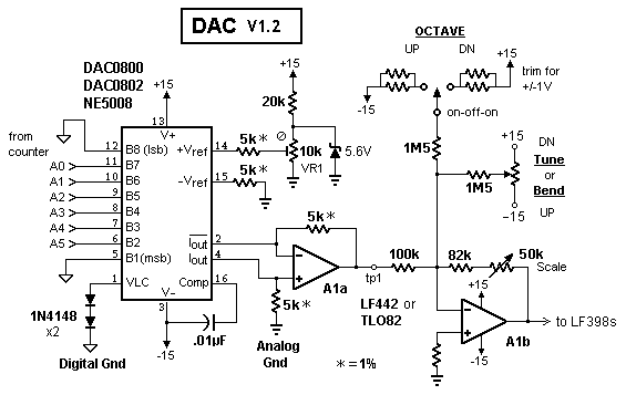
Another way to do it would be with a monolithic DAC. The old '08 series are still around.
(Electronotes gave a reason to use the "middle" 6 bits, but I don't remember what it was.) This design uses a zener diode to establish Vref and should be more precise (consider the resistor values as suggestions,) but I'm not convinced that much precision is necessary, so I'm inclined to go with the '4050 solution, even with the tedium of matching 1% resistors.
Next: Counter/KB Scan
Substitutions and pinouts
First page
Back to Projects contact: rocking softhome.net


