Elektor Formant Synth
Elektor Formant Synth
The schematics and description for the Elector Formant modular synthesizer was published in a series of Elektor magazine articles in 1977 and 1978.
They were all hand-built by people with varied levels of skill. The circuit boards and Front Panels were made available making it appealing for DIYers of even modest skills.
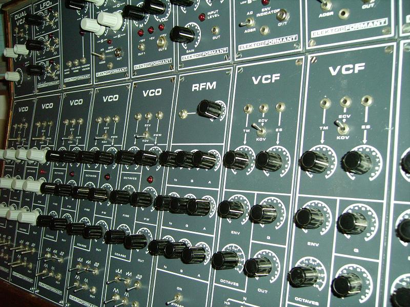
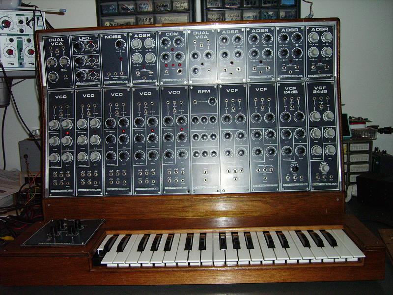
It's a modular design, but with a number of hardwired or 'normalled' connections so it can be played without doing any patching at all. The Formant is voltage-controlled to the Moog
standard of 1V/octave.
This particular instrument is a compilation of synthesizer modules which originally came from (and were presumably built in) Germany. Here's a bit of an e-mail from a friend in Belgium
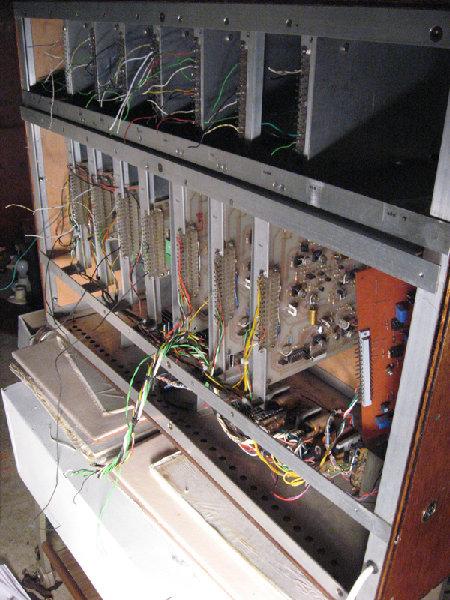
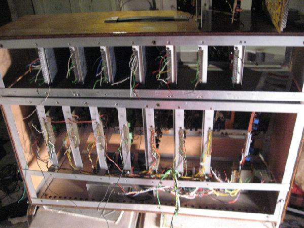
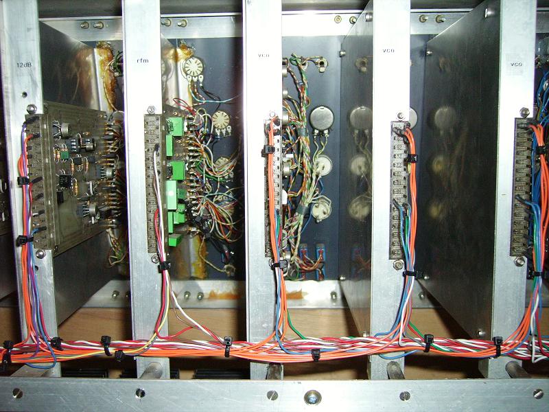
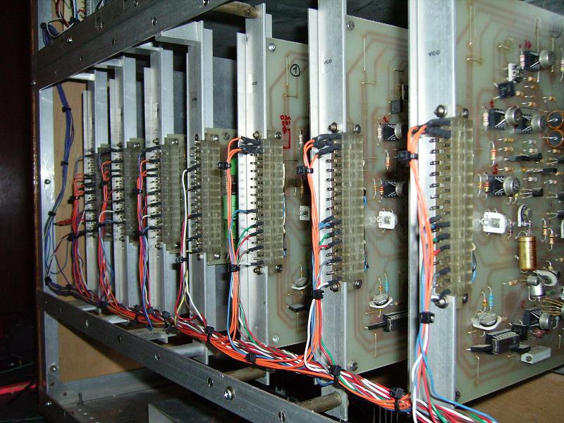
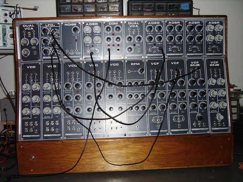
As far as I can tell it went from Germany to Belgium to California to Indiana. And now it's in the Northwoods of Minnesota. In January 2008 the Formant arrived - and the repairs began. Here's what the wiring harness looked like.
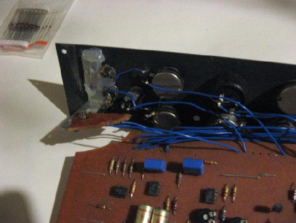
I began with work on the modules - and discovered that most of them were in fairly good shape outside of a few broken wires or bad solder joints. I replaced a few
capacitors, cleaned some connections and rewired a few LED's, Pots and Jacks.
I made a modification to each of the Envelope Generators. They are normally hardwired to the keyboard interface, but I added a jack to the front panel to allow external triggering of
the ADSR. When you patch into the external trigger jack it bypasses the internal signal. That really seemed like an oversite on the design of this ADSR.
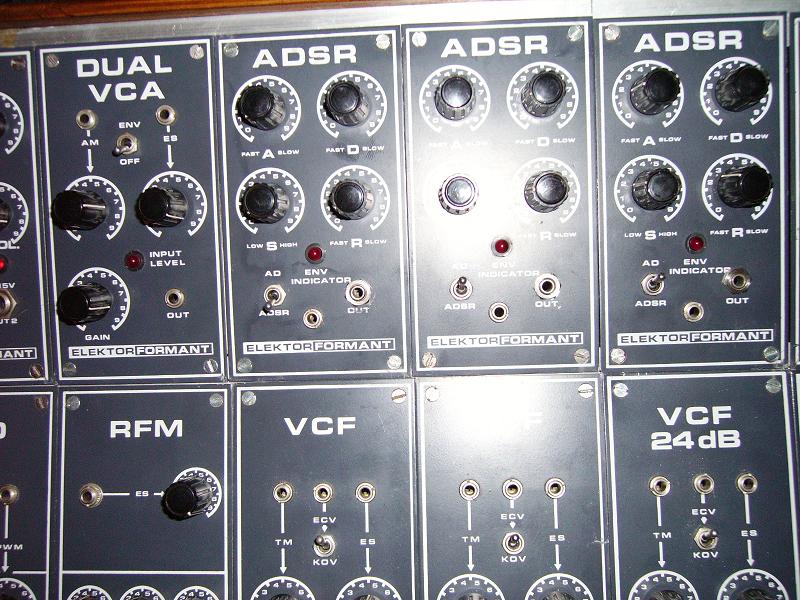
The front panels need a good cleaning and a couple of the knobs need replacing (I'd like to find all matching knobs) but it's looking a bit better now. (I still
need to come up with a "Low C" key for the keyboard.)
I was able to obtain the book (published sometime after the original articles appeared) from a friend on Electro-Music.com for payment of the shipping charges. The book describes
the keyboard, power supply, VCO, VCF, LFO, Noise, ADSR, VCA, COM (output module), RFM (Resonance Filter Module) and the 12 and 24dB VCF. It also has a section on playing
the Formant, using the modules for specific sound creation and some theory of synthesis.
There is a second book thst contains things like Ring Modulator, Envelope Follower, Mixer, Phase Shifter, ADSR Controller, VC-LFO's, Sample and Hold, but I've only been able to find a few PDF scans of it in German.
Sound Lab Ultimate Keyboard Synth